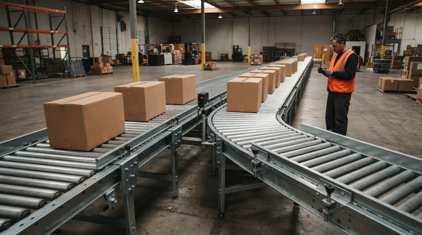
A faster belt won’t fix a bottleneck if products are already queuing at a transfer point. Effective conveyor optimization techniques start by locating where flow slows, then adjusting accumulation, layout, equipment capacity, or control logic to address the cause. Buffer zones sized for 3-5 item lengths can help absorb surges without forcing upstream sections to stop.
It’s easy to focus on the most visible slowdown, but a local change can shift the constraint elsewhere. The key is to understand how each subsystem affects the next: product spacing, transfer timing, line speed, and downstream capacity all shape total throughput.
This article explains how to identify accumulation-point bottlenecks, model conveyor subsystems, and compare existing and proposed designs before making changes. It also shows how simulation and control calibration can help coordinate starts, stops, and speeds so material moves more consistently. Use this framework to choose improvements based on system behavior, not guesswork.
Key Takeaways
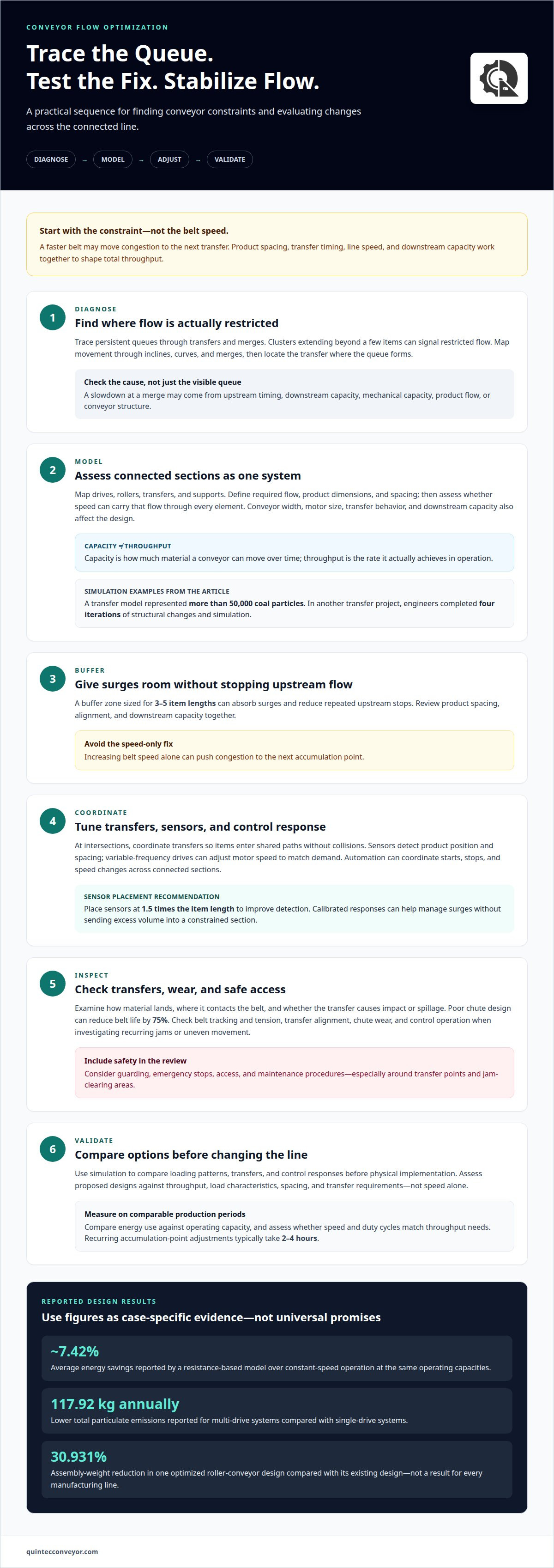
- Trace persistent queues through transfers and merges to pinpoint where flow is being constrained.
- Model connected conveyor subsystems to see how a local change may affect upstream and downstream performance.
- Compare design options against throughput, load characteristics, spacing, and transfer requirements, not speed alone.
- Use simulation and control calibration to evaluate coordinated starts, stops, and speeds before implementing system changes.
Reducing accumulation-point bottlenecks
Clusters that extend beyond a few items can signal restricted flow at a transfer or merge. A buffer zone sized for 3-5 item lengths can absorb surges and reduce repeated stops upstream. Review product spacing, alignment, and downstream capacity together; increasing belt speed alone can push congestion to the next accumulation point. At intersections, coordinate transfers so items enter shared paths without collisions.
Frequent belt stops and starts add stress and wear to system components. Conveyor controls can coordinate starts, stops, and speed, while suitable duty-cycle management helps maintain steadier flow. Proper tracking and tensioning also help prevent slippage and support smooth handling. Check these conditions when investigating recurring jams or uneven movement.
Chute design matters because abrasion at transfers can shorten belt life; poor chute design can reduce it by 75%. Examine how material lands, where it contacts the belt, and whether the transfer creates impact or spillage. Conveyor weight can also be a design consideration: one optimized roller-conveyor design reduced assembly weight by 30.931% compared with its existing design. That result describes a specific design, not every manufacturing line.
In the United States, conveyor safety requirements depend on the workplace, equipment, and task. Include guarding, emergency stops, access, and maintenance procedures in the safety review, especially around transfer points and jam-clearing areas.
Preventive maintenance should include checks of belt tracking and tension, transfer alignment, chute wear, and control operation. These inspections can reveal developing wear or blockages before they cause extended downtime. Optimization risks include jams from poor spacing, faster abrasion from misdirected product flow, and worker exposure during unsafe access or clearing.
Measure energy use against operating capacity over comparable production periods, then assess whether speed and duty cycles match throughput needs. A resistance-based model reported average energy savings of about 7.42% over constant-speed operation at the same operating capacities; multi-drive systems also reduced total particulate emissions by 117.92 kg annually compared with single-drive systems.
Investigate accumulation points where clusters are longer than a few items; adjustments typically take 2-4 hours. Reducing shutdown and restart events can limit belt stress and wear, while helping avoid reduced throughput, longer travel times, and premature system ageing.
Simulation and calibration of control strategies
Simulation lets engineers test how a conveyor system responds before changing equipment or control logic. A transfer model represented more than 50,000 coal particles moving between conveyors.
Simulating Critical Design Parameters
Computer simulation represents conveyor components and operating conditions so engineers can assess how design changes affect flow. A model can test loading patterns, transfers, and control responses under different operating scenarios.
This is valuable when changing one element could disrupt another. In one transfer project, engineers made four iterations of structural changes and simulation to find a solution. Virtual testing helps compare alternatives before physical implementation and examine product volume, transfer behavior, and equipment interactions across applications.
Calculating Capacity and Belt Speed
Capacity is the amount of material a conveyor can move over time, while throughput is the rate it actually achieves in operation. Required belt speed depends on target throughput and product spacing, so evaluate them together.
For a useful model, define the required flow, product dimensions, and spacing, then assess whether the selected speed can carry that flow through every conveyor element. Conveyor width, motor size, and downstream capacity also affect the design. A speed that meets the target rate in one segment may cause accumulation at a slower transfer, so test the connected system rather than isolated equipment.
Calibrating Loads and Operating Controls
Calibration sets operating speed and loading conditions to move products efficiently without unstable handling or spillage. Loading limits depend on conveyor capacity, belt design, product characteristics, and transfer geometry. Simulation can test how these factors affect flow.
Sensors detect product position and spacing, while variable-frequency drives adjust motor speed to match operating demand. Automation can use those signals to coordinate starts, stops, and speed changes across connected sections. Sensor placement at 1.5 times the item length is recommended to improve detection. Calibrating this control response helps manage surges without sending excess volume into a constrained section.
Where control changes intersect with equipment design, conveyor system integration can help align the modeled strategy with the operating layout.
Bottleneck analysis and subsystem modelling
Optimize routing by mapping material movement through inclines, curves, and merges, then identifying transfers that create queues. Consolidating routes where practical can reduce transfer points. Subsystem analysis can also reveal whether a constraint stems from mechanical capacity, product flow, or conveyor structure.
Subsystem modelling divides a connected line into sections such as drives, rollers, transfers, and supports. Engineers can assess how each element affects the whole system instead of treating a visible queue as an isolated problem. For example, a slowdown at a merge may stem from upstream timing or downstream capacity. Mapping product movement and queue locations helps distinguish the causes and focus engineering analysis.
Modal analysis examines a structure’s natural frequency, which describes how it responds to vibration. A roller-conveyor study conducted 150 simulations for linear static analysis and reported a natural frequency of 54.34 Hz for its existing design and 49.928 Hz for its optimized design. Comparing those results helps engineers assess how a design change affects structural response, alongside operating requirements.
Static structural analysis estimates how a conveyor structure responds to a defined load. In the same study, engineers applied approximately 350 kg, or 3500 N, to four rollers at the model’s center. This example shows why load position matters: stress and deflection depend on where force enters the frame, as well as on the arrangement of rollers and supports.
Coal flow analysis examines how bulk material moves through a transfer, including its trajectory and contact with chute surfaces. Modelling particle movement helps engineers assess whether a chute guides material toward the receiving belt or causes impact and buildup. The findings can inform changes to chute geometry and transfer alignment before physical modifications.
Use subsystem results together: a modal or static result alone cannot establish throughput. Comparing structural analysis with flow behavior and route constraints gives engineers a clearer basis for selecting changes that address the actual bottleneck.
Optimized conveyor rollers weighed 72.20 kg, bearings 3.050 kg, chassis C-channels 25.30 kg, and shafts 20.75 kg in the physical model. A resistance-based energy model identified indentation rolling resistance, bulk solid flexure resistance, and secondary resistance as contributing 89% of resistance to motion in the studied belt conveyor system. Load analysis should consider materials’ weight, size, shape, texture, and product orientation requirements.
Comparison of existing and optimized designs
Compare the existing layout with a proposed design using the same load, operating conditions, and throughput target. This shows whether a change improves material handling without creating a new constraint.
Comparing Conveyor Types and Strategies
Design comparison evaluates how each conveyor type transports its intended material and where its constraints arise. The method matters because changing speed or layout will not address every application in the same way.
A belt conveyor suits continuous transport along a defined route, so compare belt speed, loading, and transfer geometry. Roller conveyors are typically used for heavy items with flat bottoms; assess roller spacing and how loads move across transfers. Chain conveyors can move very heavy loads, including full pallets, so compare capacity with load weight and route needs. For screw conveyors, evaluate how the material and conveying path affect movement through the equipment. Across all types, compare the existing design with alternatives under equivalent operating conditions.
Assessing Upgrade Costs and ROI
ROI compares the value of an upgrade with its project cost, helping prioritize changes with a clear operational purpose. A useful calculation considers throughput, energy use, maintenance, and downtime before and after the change.
Project price depends on the scope of redesign, equipment, controls, installation, and facility requirements, and is provided after a quote request. Separate expected gains by source: increased transport capacity, reduced energy demand, or fewer maintenance interruptions. Then compare those gains with the project cost over the same operating period. This makes the rationale transparent without treating a modeled improvement as a guaranteed result.
Transfer-chute geometry also deserves direct comparison. Assess how each proposed chute guides material onto the receiving belt, and whether its height, angle, and shape could cause spillage, buildup, or uneven loading. A design review should account for product characteristics and route geometry rather than selecting a chute by shape alone. Comparing these conditions helps determine whether a proposed change supports consistent transport through the transfer.
For a project-level comparison of existing and proposed conveyor layouts, discuss a conveyor design review.
Quintec Conveyors: Conveyor Maintenance
Quintec Conveyors can help when recurring belt wear, tracking issues, or transfer problems limit throughput. Its preventive maintenance for material handling systems addresses equipment condition, while conveyor integration and material handling solutions can support broader system needs.
Turn to Quintec when maintenance findings point beyond an isolated component, such as when repeated stoppages stem from layout, equipment, or control interactions. For projects involving connected equipment or facility requirements, Robotics & Automation and Infrastructure solutions can also help.
Share the operating challenge and affected conveyor area to start a focused discussion about next steps. Contact Quintec Conveyors to discuss your conveyor maintenance needs.
Build the Next Improvement Into Your System
Throughput gains are easier to sustain when optimization becomes part of how a facility plans future changes, rather than a one-time response to a jam. Use operating observations to guide the next engineering decision, and account for how equipment, controls, and facility infrastructure work together as needs evolve. This systems-level perspective makes conveyor optimization techniques a practical basis for long-term planning.
Quintec Conveyors brings together conveyors, Robotics & Automation, and infrastructure for industrial material handling projects. If you’re considering a change to an existing operation or planning a new system, identify the constraint you want to address and the outcome the project needs to support. This gives the discussion a clear operational starting point.
Discuss your conveyor project with Quintec Conveyors and take the next step toward a more deliberate, capable material handling system.
Frequently Asked Questions
What are the best techniques for optimizing conveyor system performance?
The best conveyor optimization techniques address the limiting condition in the actual operating mix. Separate recurring constraints from temporary surges, such as a heavier product mix or a receiving-area delay. Prioritize changes whose effects can be measured at both the affected conveyor and its downstream destination. Reassess the result under comparable operating conditions before extending a change across the line.