Conveyor Drives: Matching Drive Systems to Industrial Conveyor Demands
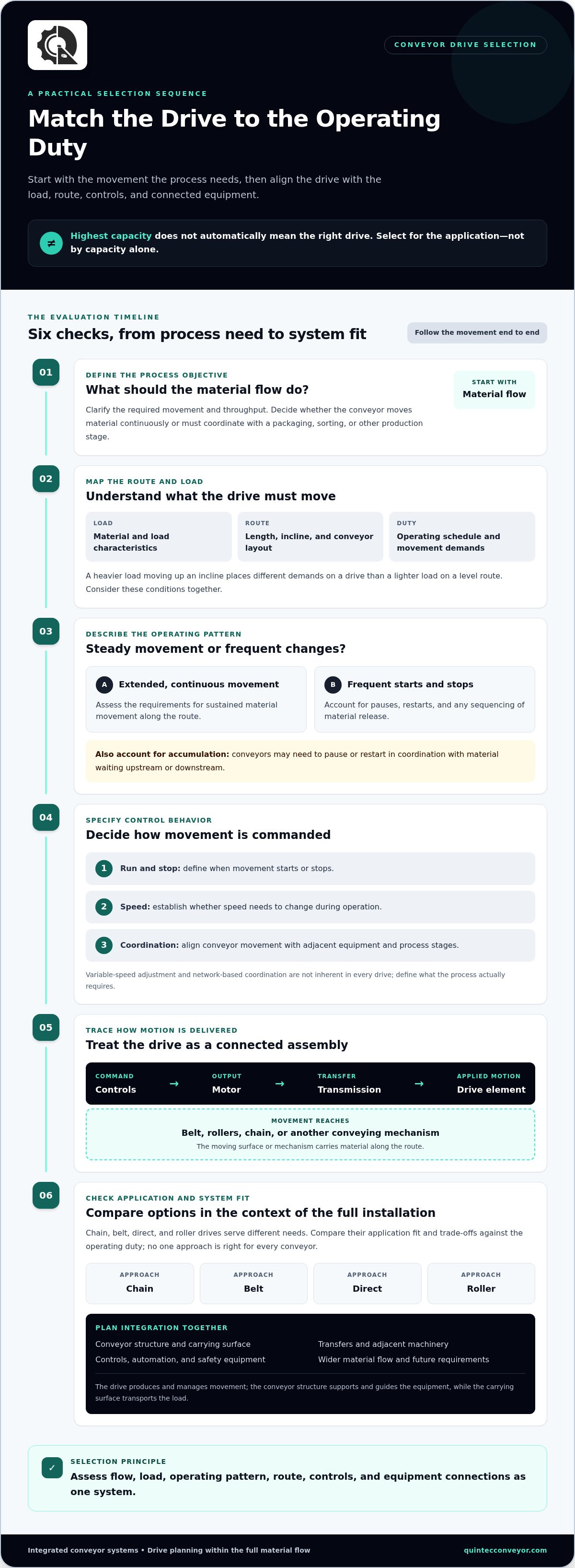
The drive with the highest capacity isn’t automatically the right choice for a conveyor. A mismatch between the drive arrangement and the load, route, speed requirements, or control strategy can affect how reliably the full line moves material. Selecting conveyor drives is less about finding a universally best option and more about matching the system to its operating duty.
Comparing options can be challenging because chain, belt, direct, and roller drives serve different needs. The drive also has to work with the motor, controls, conveyor structure, and wider material-handling process. Evaluating any one component in isolation can obscure what the conveyor actually requires.
This guide explains how conveyor drives contribute to system performance, compares common approaches, and outlines practical factors for evaluating which may suit your application. It also covers why load conditions, facility layout, controls, and future requirements belong in the same selection process. Quintec Conveyors designs, engineers, and installs integrated conveyor systems, bringing drive planning into the context of the complete material flow.
Key Takeaways
- Separate the drive’s role in producing and managing movement from the conveyor structure and load-carrying surface.
- Trace how control commands, motor output, mechanical transmission, and the conveyor’s drive element work together.
- Compare conveyor drives by application fit and trade-offs rather than assuming one approach suits every duty.
- Assess flow objectives, operating patterns, route, load, control requirements, and connections to adjacent equipment before selecting a drive.
- Plan drive integration alongside conveyor layout, controls, automation, and material flow to support a coordinated system.
Conveyor Drives in Industrial Material-Handling Systems
A conveyor drive is the system that produces and manages conveyor movement. It supplies motion and coordinates how that motion is applied, helping the conveyor start, stop, and run according to process requirements. A drive is more than a motor: it is part of the operating system that connects the required movement to material flow.
The drive is distinct from the conveyor structure, which supports and guides the equipment, and from the belt, rollers, or other surface that carries the load. A complete installation may also include controls, safety equipment, transfers, and interfaces with adjacent machinery. A Conveyor System Overview offers broader context on how conveyor types move materials. Drive planning focuses on how a particular conveyor receives and manages motion.
What components make up a conveyor drive system?
Drive components work together to convert a control instruction into movement. Their arrangement varies by conveyor design, so it helps to understand each component’s role without assuming a standard configuration.
- Motor: Provides the mechanical output that initiates movement.
- Transmission components: Transfer motion from the motor to the conveyor’s drive arrangement.
- Drive element: Applies motion to the conveyor, moving its carrying surface or other conveying mechanism.
- Controls: Coordinate when movement begins or stops and, where required, how it is managed during operation.
Together, these elements form a connected chain. The drive element transfers motion into the conveyor, while the structure and carrying surface support and convey the load. The specific components and their relationships depend on the conveyor’s design and intended duty.
How does a drive affect conveyor operation?
A drive produces and regulates conveyor movement; the conveyor supports, guides, and transports the conveyed material. This distinction matters during planning. The conveyor’s physical path and load-carrying design define what it must move, while the drive arrangement determines how motion is applied to meet process requirements.
Drive behavior influences how a loaded conveyor starts, how it runs, whether its speed needs to change, and how it stops. These details can affect how material arrives at a transfer point or aligns with the next production stage. For example, a line coordinated with a packaging or sorting process has different control considerations from one that moves material continuously between two points.
Requirements depend on the load, duty cycle, route, and control needs. A long route, frequent starts and stops, or changing material flow can shape drive requirements differently from steady movement along a short path. Assess these conditions together with throughput and conveyor design. There is no universal drive setup: effective selection starts with the task, then considers how the drive fits the conveyor and the wider material-handling installation.
How Conveyor Drives Transfer Motion and Respond to Operating Demands
Motion begins with an operating command. A control device signals the drive to run or stop, and the motor produces mechanical output. Transmission components carry that output to the conveyor’s drive element, which applies force to the belt, rollers, chain, or other conveying mechanism. The moving surface then carries material along the route. The exact arrangement depends on the conveyor design and system configuration.
Each stage affects the next. The motor must provide motion suited to the task, the transmission must deliver it to the drive element, and the element must engage with the conveyor as intended. A change in one part of this chain can affect how movement is delivered. Consider conveyor drives as coordinated assemblies rather than standalone motors.
How do controls shape conveyor drive behavior?
Controls determine when a movement command is issued and, where the system supports it, how operating speed is adjusted. A line that starts and stops to release products in sequence has different control demands from one intended for steady transport. Accumulation areas also affect planning because conveyors may need to pause or restart in coordination with material waiting upstream or downstream.
Variable-speed adjustment and network-based coordination aren’t inherent in every drive. Define the required control behavior based on the process, including how movement relates to adjacent equipment. MHI’s Conveyor and Sortation Systems Industry Group provides industry resources covering training, inspection, safety, and maintenance, which are important to the broader operation of conveying systems.
How do conveyor layout and load conditions matter?
Load characteristics, route length, incline, and operating schedule shape the work the drive must perform. A conveyor moving heavier items up an incline has different demands from one carrying lighter items along a level route. Frequent starts and stops can also call for different operating behavior from extended, continuous movement. Assess these factors together rather than treating them as separate equipment decisions.
Drive requirements emerge from the combination of operating duty and conveyor layout, because each determines how motion must be delivered across the route.
Transitions matter, too. A transfer to a robot, sorter, or another conveyor may require movement to align with the next process. Accumulation or merging points can affect when and how sections operate. For example, a conveyor feeding a robotic picking cell needs to fit the cell’s material flow and control sequence, not simply move items along its own path. Quintec’s integrated conveyor systems bring drive planning into the wider design of material handling, controls, and automation. Coordinating these elements helps the system support the intended process from its first movement through the handoff to the next operation.
Comparing Conveyor Drive Approaches by Application and Trade-Off
Drive comparisons are most useful when they distinguish the mechanical arrangement from the way movement is controlled. A geared drive describes how motor output is transmitted. Variable-speed control describes how operating speed can be adjusted, where the system supports it. Motor-driven rollers distribute drive power across roller sections. These approaches can be combined, so start comparisons with the conveyor’s layout, load, operating pattern, and integration needs.
| Approach | Potential application fit | Control and layout considerations | Load and integration questions |
|---|---|---|---|
| Geared drive arrangement | May suit a conveyor section where a drive and transmission serve a defined conveying path. | Consider drive placement, access for maintenance, and whether connected sections need coordinated movement. | Assess the duty and how motion transfers to the conveyor. Coordinate interfaces with adjoining equipment. |
| Variable-speed control | May be useful when the process requires conveyor speed adjustment rather than one fixed operating rate. | Control requirements depend on the system configuration. Plan how speed changes relate to upstream and downstream processes. | Consider how the load and operating pattern affect the movement required across the route. |
| Motor-driven rollers | May fit layouts where roller sections or zones need drive power distributed along the conveyor. | Zone-level movement and accumulation can be design considerations, depending on the system and controls. | Plan roller sections around the conveyed items, transfers, and connections to other equipment. |
When might a centralized drive arrangement fit?
A centralized arrangement may suit a connected conveyor section when its movement can be managed around a shared drive location. Assess whether the layout provides suitable maintenance access and how much coordination is needed between sections. The choice depends on conveyor design and operating duty, not on a general assumption that one arrangement is more reliable or efficient.
When might distributed or motor-driven rollers fit?
Motor-driven rollers distribute drive power across roller sections, which can support a design organized into zones. Designers can consider whether sections should move together or operate separately to manage accumulation and transfers. Those functions depend on the complete configuration and controls, not on the roller concept alone. A dedicated MDR conveyor systems guide can explore the approach in greater technical detail.
Motor choice is another part of the design, but it shouldn’t be confused with the drive arrangement or control strategy. A focused conveyor motors guide can address motor types and selection without treating them as interchangeable with geared or roller-based architectures. Safety planning also belongs in the comparison. OSHA’s conveyor safety regulations address conveyor equipment in marine terminals, so apply requirements in the relevant operating context.
No approach is universally superior. Compare how each fits the material flow, access needs, control behavior, and adjacent equipment. Quintec’s integrated conveyor systems bring those considerations into a coordinated design, aligning drive decisions with the wider material-handling process.
How to Evaluate Conveyor Drives for Your Facility
A useful drive assessment starts with the process, not a component catalogue. Define what the conveyor must move, how material should flow, and how the equipment will operate before comparing alternatives. This gives the project team a common basis for evaluating conveyor drives as part of an integrated material-handling system.
- Define flow objectives and operating duty. Document the intended material flow, planned throughput, operating schedule, and expected pattern of use. Clarify whether movement is steady, intermittent, or coordinated with other process steps.
- Describe the load. Record material characteristics that affect conveying, such as item dimensions, weight range, and how products are presented to the conveyor. Include changes in the load profile if different items share the line.
- Map the route and facility constraints. Identify the conveyor path, inclines, transfers, available space, and access needed around equipment. Note how the proposed route fits the facility and its existing material-handling systems.
- Document control and equipment interfaces. Map start and stop points, accumulation areas, handoffs, and connections to automation or adjacent equipment. Establish how coordinated movement should support the process.
- Include maintainability and future needs. Consider access to drive components for inspection and maintenance, as well as anticipated operational changes. Ground future requirements in known plans rather than assumptions about expansion.
Which operating requirements should teams document?
Bring the process map and operating details together in one project record. Show where material enters and leaves, how it moves between operations, and where pauses, transfers, or accumulation may occur. Include planned throughput and operating hours alongside facility constraints. This shared reference helps engineering teams connect the drive decision to process requirements, layout, and the wider system.
How can teams compare options consistently?
Use a decision matrix to assess each candidate against the same scenario and system boundaries. A simple rating scale can help identify trade-offs, provided the team records the evidence and assumptions behind each rating. Treat the score as a comparison aid, not a final answer.
- Application fit: Does the arrangement suit the documented load, route, and duty?
- Controls: Does it support the required start-stop behavior and coordination?
- Integration: How does it interface with transfers, automation, and adjacent equipment?
- Access: Can teams reach relevant components for inspection and maintenance?
- Maintainability: What service considerations follow from the proposed configuration?
Compare like with like. A broader view of layout, process, and equipment interfaces is covered in the industrial conveyor systems executive guide. Drive architecture assessment is also distinct from motor sizing and reducer calculations, which require project-specific engineering based on the complete design. For a coordinated evaluation, explore integrated conveyor engineering with Quintec.
Integrating Conveyor Drives Into a Reliable Material-Handling Solution
A drive decision affects more than the movement of one conveyor. It influences how equipment responds to controls, hands material to the next process, and fits into the facility’s overall flow. Planning conveyor drives alongside conveyor layout, controls, and operating objectives helps teams define equipment interfaces early instead of treating the drive as a component choice disconnected from the system.
What does system-level drive integration address?
Integration planning considers how conveyor sections work together, where material transfers, and how each section coordinates with controls and connected equipment. For example, a conveyor feeding an automated process needs defined handoff conditions so material movement aligns with the next operation. Clear interfaces help teams understand how equipment should interact and which operating requirements need to be addressed.
- Conveyor sections: Clarify which sections operate together and how their movements relate.
- Transfers and connected equipment: Define how material moves between conveyors, robots, sorters, or other handling equipment.
- Controls: Align commands and operating sequences with material flow and process needs.
Flexibility is also a design consideration when future changes are relevant. A modular conveyor systems guide explores how modular design can support planning for changing system needs. Process engineering adds another perspective by connecting equipment decisions to the flow and objectives of the operation, not simply the capabilities of an individual machine.
How does Quintec support conveyor system planning?
Quintec designs, engineers, and installs custom conveyor systems, considering how equipment fits into the wider material-handling process. This system-level view brings conveyor layout, drive requirements, facility infrastructure, controls, and equipment interfaces into the same project conversation. The goal is to define a solution around operating requirements and the relationships between system components.
Project needs may also involve warehouse automation, robotics, or other material-handling equipment. Quintec’s capabilities in these areas, along with process engineering and conveyor maintenance, support teams planning connected systems and considering ongoing equipment needs. The team brings more than 100 years of collective industry experience to its design, engineering, and installation work, while recognizing that project requirements differ.
Start with the movement the process needs, then plan how the conveyor and its interfaces will support it. Discuss your conveyor integration project with Quintec to explore a system designed around your material-handling objectives.
Turn Drive Planning Into a Clear Next Step
A well-planned conveyor project starts with a practical question: what should material movement make possible across your operation? Use that objective to guide planning, bringing together process priorities, facility constraints, and the interfaces that matter. This keeps conveyor drives in perspective as part of a larger operational plan, where equipment decisions need to support the way work flows through the facility.
Before moving into design, align stakeholders on the outcome the system needs to support and the conditions it must accommodate. A shared understanding connects day-to-day operating needs with decisions about layout, controls, and integration. It also gives the project team a stronger basis for evaluating options as requirements develop.
Quintec can help translate those priorities into a considered conveyor system plan. Discuss your conveyor system requirements with Quintec and take the next step toward a material-handling solution shaped around your operation.
Frequently Asked Questions
What is a conveyor drive?
A conveyor drive is the equipment and control arrangement that makes a conveyor move. It typically includes a motor, components that transmit motion, and a mechanism that applies movement to the conveying surface. The term can mean different things in different technical contexts, so project documents should state whether “drive” refers to the complete arrangement or a specific component. Clear terminology helps operations, engineering, and maintenance teams discuss the same equipment.
What is the difference between a conveyor motor and a conveyor drive?
A conveyor motor produces mechanical output, while a conveyor drive generally describes the arrangement that uses that output to move the conveyor. The drive may include the motor, transmission components, the mechanism that engages the conveyor, and associated controls. Replacing a motor, for example, doesn’t necessarily change the drive architecture. Keeping the terms distinct helps teams identify whether a design question concerns the motor alone or how power reaches the conveyor.
How do I choose a drive for an industrial conveyor?
Start by describing the actual task: what the conveyor carries, how material arrives, and how it must be handed off. Then compare drive arrangements against that operating scenario, considering control behavior, equipment interfaces, and maintenance access. A line that feeds several process stations, for instance, may need different coordination from a conveyor serving one transfer point. Final component sizing should follow engineering review of the complete conveyor design.
Can conveyor drives control conveyor speed?
Some conveyor drive configurations support speed adjustment, depending on the selected drive and control system. If a process needs different speeds for product handling or coordination with another machine, identify that requirement before specifying equipment. A fixed-speed arrangement may suit a consistent movement task, while a system designed for adjustment can address changing process demands. Plan speed control with connected equipment rather than in isolation.
What factors affect conveyor drive selection?
Selection depends on the conveyed material, its load characteristics, the conveyor’s path, and how the equipment operates during a typical shift. Starts and stops, inclines, transfer points, and connections to other machinery can all affect what the system must do. Facility constraints matter, too: restricted access may influence where equipment can be positioned or serviced. Documenting these details gives the engineering team a clearer basis for comparing drive arrangements.
How do motor-driven roller conveyors differ from other drive arrangements?
Motor-driven roller conveyors distribute drive power among roller sections rather than relying only on a single drive point for a conveyor path. Depending on the design and controls, sections may be planned as zones that operate together or separately. This can matter where item spacing, accumulation, or transfers need attention. Assess the arrangement against the conveyed products and process sequence, since zone behavior depends on the system configuration.
When should conveyor drive selection be part of a system integration project?
Include drive planning early if a conveyor must coordinate with robotics, automation, sortation, or several connected process stages. Early planning helps define handoff points, control interfaces, equipment space, and how operating sequences relate across the line. It is especially useful when a new conveyor connects to existing equipment, since the interface can shape the design on both sides. Treating the drive as part of integration supports informed decisions across the material-handling process.