Conveyor Motors: A 2026 Guide to Performance, Selection, and System Efficiency
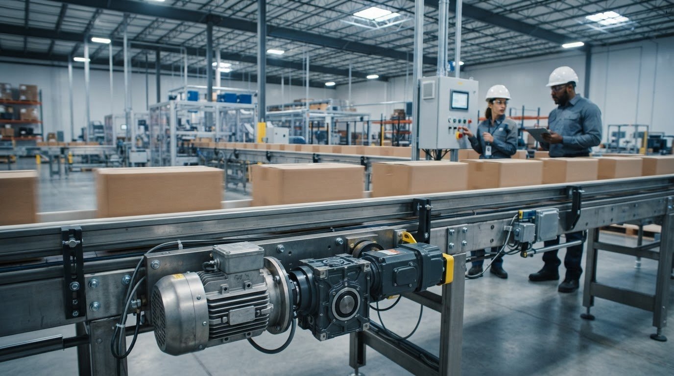
The most powerful motor isn’t always the right choice for a conveyor. The right conveyor motors match torque and speed to the load, material flow, and operating demands, while also fitting the conveyor and its controls. Choosing well can be difficult when specifications use unfamiliar terms or describe a motor without explaining how it works within the full system.
When comparing options, look beyond motor size alone. A mismatch can limit throughput or contribute to avoidable operating issues, even when a motor appears suitable on paper. This guide explains how motors, gearmotors, reducers, and drives work together, and which application conditions affect selection.
Motor decisions also connect to conveyor layout, facility workflow, equipment integration, and operational objectives. Because performance depends on the complete system, not a component in isolation, Quintec Conveyors designs, engineers, and integrates custom conveyor systems, drawing on more than 100 years of collective industry experience. This system-level approach provides a practical framework for evaluating motor requirements as part of a reliable conveyor design.
Key Takeaways
- Compare conveyor motors by application and control requirements, not by rating alone.
- Assess load, speed, duty cycle, and operating conditions to identify a suitable motor arrangement.
- More horsepower doesn’t automatically improve performance; excess capacity can create design and control tradeoffs.
- Account for how motors, gearmotors, reducers, and drives work together in the conveyor system.
- Connect motor selection to conveyor layout, controls, adjacent equipment, and facility workflow for a more reliable design.
Conveyor Motors in Industrial Material-Handling Systems
Conveyor motors convert electrical energy into rotational force that moves a conveyor and its load through a material-handling process. The motor supplies motion; the conveyor’s mechanical design determines the route, direction, and transfer points. A belt conveyor, for example, carries items on a moving belt, while a roller conveyor moves them across rotating rollers.
This distinction matters when planning a system. The motor provides the input, but the belt, rollers, frame, pulleys, and other components determine how that input becomes useful movement. The Conveyor System Overview provides broader context on conveyor types and applications. For project design, the key question is how the motor arrangement supports the specific conveyor and facility workflow.
How a conveyor motor turns power into material movement
A motor’s rotating shaft transfers power to conveyor components, often through a gearbox, coupling, chain, or belt. On a belt conveyor, the motor turns a drive pulley, which moves the belt and carries material. In other configurations, motor power turns rollers or another conveying mechanism.
Two terms help describe this action: torque is rotational force, and speed describes how quickly the output turns. Together, they help determine whether a conveyor can start and move its intended load at the required pace. Consistent movement supports the process, whether material needs to reach a packing area steadily or transfer between connected stages without interrupting workflow.
Conveyor motor versus gearmotor, reducer, and drive
These terms describe related but distinct parts of a system. Knowing the difference makes specifications easier to compare and keeps the focus on the complete conveyor arrangement, rather than treating every component as a motor.
- Motor: Produces rotational motion and supplies mechanical power.
- Gearmotor: Combines a motor and gearbox in one assembly, providing a compact arrangement for applications that need reduced output speed and increased torque.
- Reducer: A gearbox that changes output speed and torque. It may be integrated with a motor or installed as a separate component.
- Drive: Equipment that controls or adjusts motor operation. Depending on the system, it can regulate motor speed or manage how the motor starts and runs.
These components work together. A drive affects how motion is controlled, while the motor and gearing deliver it to the conveyor mechanism. For reliable material flow, their roles need to align with the conveyor layout and intended operating process.
Common Conveyor Motor Types and Where Each Fits
Motor arrangements differ in how they deliver motion and how much control they provide. The best fit depends on the conveyor’s task, operating profile, and relationship to other equipment. Comparing options in context is more useful than choosing from a product category alone.
| Type or arrangement | Typical use | Potential advantage | Design consideration |
|---|---|---|---|
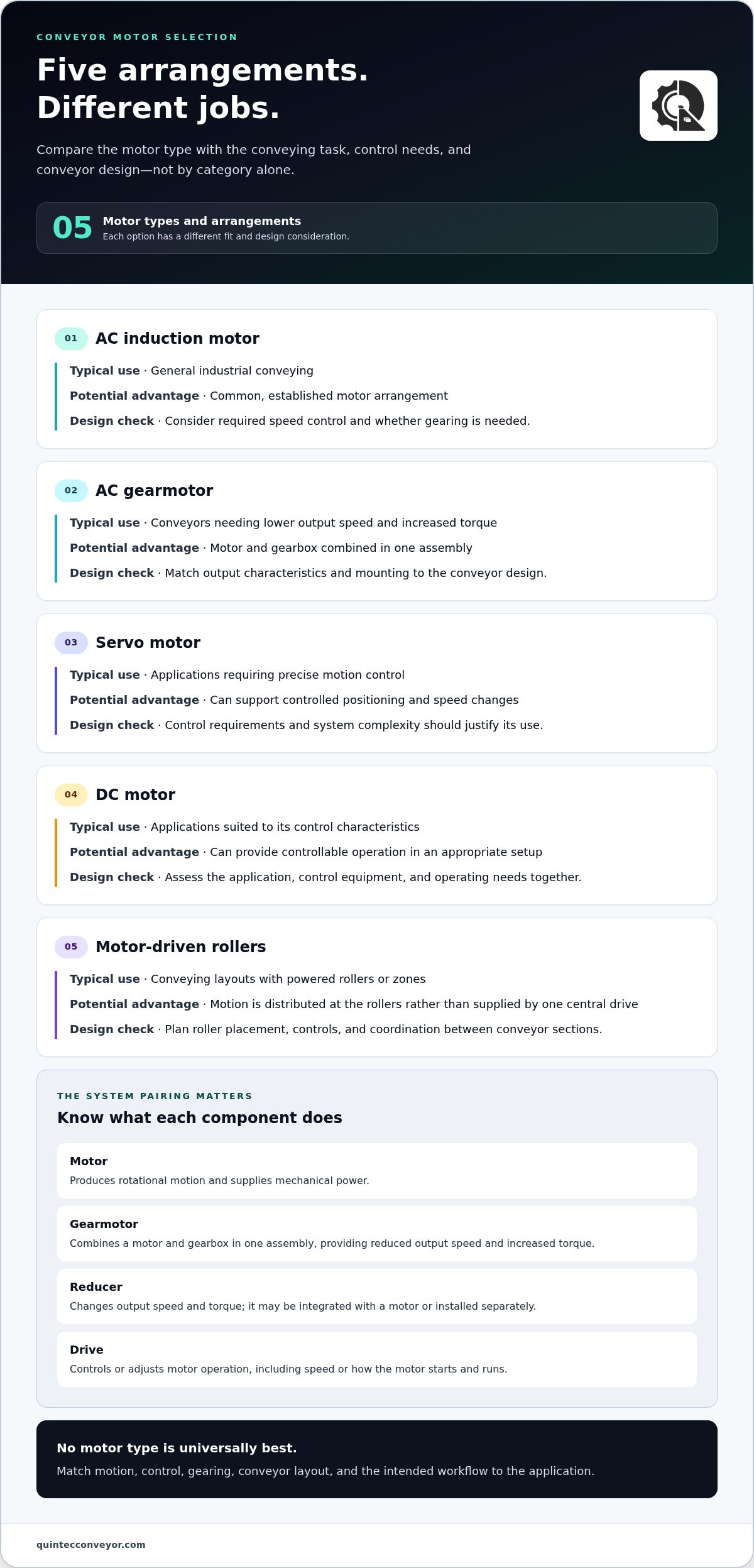
| AC induction motor | General industrial conveying | Common, established motor arrangement | Consider required speed control and whether gearing is needed |
| AC gearmotor | Conveyors needing lower output speed and increased torque | Motor and gearbox are combined in one assembly | Match output characteristics and mounting to the conveyor design |
| Servo motor | Applications requiring precise motion control | Can support controlled positioning and speed changes | Control requirements and system complexity should justify its use |
| DC motor | Applications suited to its control characteristics | Can provide controllable operation in an appropriate setup | Assess the application, control equipment, and operating needs together |
| Motor-driven rollers | Conveying layouts with powered rollers or zones | Motion is distributed at the rollers rather than supplied by one central drive | Plan roller placement, controls, and coordination between conveyor sections |
AC induction motors and gearmotors
AC induction motors are commonly used in industrial equipment, including conveyor applications. If the motor’s direct output speed doesn’t suit the conveyor, a gearbox can reduce speed and change the torque available at the output. A gearmotor packages these elements together; a separate reducer is another possible arrangement. The operating profile and conveyor design determine which configuration fits.
Servo, DC, and motor-driven roller arrangements
Servo motors may suit applications where accurate speed or position control is central to the process. DC motors are another option when their operating and control characteristics fit the application. Motor-driven rollers differ from a centrally driven conveyor: powered rollers provide motion at points along the conveying path, which can support a layout organized into controlled sections.
These options aren’t interchangeable, and no type is universally best. A conveyor moving products steadily between process stages, for example, may have different control needs from a system that must position items precisely. In each case, consider conveyor motors and controls together, alongside adjacent equipment and the intended workflow.
System integration also means considering how mechanical equipment operates safely within the broader material-handling environment. The OSHA Regulations for Material Handling provide a regulatory reference for material handling and storage. For a project-level view, custom conveyor system engineering brings motor arrangements into the wider design discussion.
How Load, Speed, and Duty Cycle Shape Conveyor Motor Selection
Choosing a motor by horsepower alone can overlook the demands that determine how a conveyor performs in operation. Start with the complete application: the material being moved, the required flow, the conveyor’s mechanical arrangement, and how the system will be controlled.
Motor output must match the conveyor’s load, speed, and operating pattern to deliver the movement the process requires. A rating that looks suitable in isolation may not account for starting under load, an incline, frequent stops, or the controls needed to coordinate with connected equipment.
Load, conveyor speed, and start-stop demands
Document what the conveyor will move and how it will move it. The material’s weight and type, unit-load dimensions, accumulation, incline, and conveyor length all affect the effort required. A long or inclined conveyor, for example, can place different demands on a motor arrangement than a short, level run.
Required throughput informs the target conveyor speed, which in turn affects motor output and any reducer arrangement. The operating sequence matters as well. Frequent starts and stops, reversals, or controlled acceleration can change what the motor and controls need to do, particularly when the conveyor starts with product already on it.
Duty cycle, environment, and control requirements
A motor must suit the way production actually runs, not just the planned average. Engineers consider operating hours, shifts, idle periods, and peak-demand patterns. Intermittent operation and sustained use create different equipment-selection requirements, so documenting the production schedule helps ground the design in actual operating needs.
The installation environment matters too. Dust, temperature, washdown, and other site conditions can affect equipment selection and protection. Control requirements add another consideration: determine whether the conveyor needs variable speed, synchronization with adjacent machinery, or precise positioning. These needs influence the motor arrangement and the drive or control equipment designed around it.
Before recommending a configuration, engineers gather application details such as:
- Material type, unit load, and accumulation conditions
- Conveyor length, incline, layout, and conveying mechanism
- Required throughput, operating speed, and start-stop sequence
- Hours of operation, production peaks, and environmental exposure
- Control needs, including speed adjustment and coordination with connected equipment
These inputs make motor selection a system-engineering decision, not a simple comparison of horsepower figures. Accurate application data and qualified engineering review are important because assumptions about load or operating sequence can lead to a poor match. Evaluating conveyor motors as part of custom conveyor design also connects component choices to facility workflow and the expected performance of the integrated system.
Why More Horsepower Is Not Automatically a Better Conveyor Motor
A higher horsepower rating doesn’t guarantee better conveyor performance. Horsepower describes a motor’s power capacity, but it doesn’t show on its own whether the motor can deliver the required torque at the needed speed, respond appropriately to the controls, or suit the conveyor’s operating pattern. A reliable match comes from the system’s actual demands, not from choosing the largest rating available.
Extra capacity may be appropriate when the application requires it, but it can also introduce tradeoffs. The motor, reducer, drive, and conveyor structure must work together, and a larger motor won’t correct a poor conveyor layout or unsuitable material flow. Depending on the application, excess capacity may complicate control decisions or mean the motor operates away from its intended duty point. Energy use also depends on the complete system and how it runs, so a larger rating alone doesn’t establish better efficiency.
Motor ratings versus the actual conveyor operating point
Rated power is only one part of the selection picture. Torque, output speed, load profile, and the conveyor’s mechanical arrangement all affect the operating point the motor must support. A level conveyor carrying a steady load presents different demands from one that starts under load, handles accumulation, or follows an incline. Those differences help determine motor and reducer requirements.
Generic sizing formulas can mislead if their assumptions don’t reflect the actual application. Engineers need operating data and a clear understanding of the conveyor design before assessing the required motor arrangement. The industrial conveyor systems integration guide explains how component decisions fit within a complete system.
When controls and system design matter as much as motor size
Controls shape how a motor starts, runs, and adjusts to process needs. A drive may support speed adjustment, while the control sequence coordinates movement with upstream or downstream equipment. If connected conveyors don’t transfer material at compatible rates, increasing motor horsepower alone won’t resolve the flow issue. Consider the system’s operating sequence and transfer points alongside motor capacity.
Configuration matters, too. A modular conveyor systems guide can help frame how conveyor sections fit together as workflows change. Selecting conveyor motors in this wider context helps align motor output, controls, and layout with operational objectives. For a project-level assessment, integrated conveyor system design brings these considerations into the engineering process.
Integrating Conveyor Motors into a Reliable System Design
A motor decision is only one part of a dependable conveyor system. Performance depends on how the motor works with the conveyor layout, control sequence, connected equipment, and material flow across the facility. Treating these elements as one design problem helps ensure the selected arrangement supports operating needs from project planning through installation.
A project sequence for defining motor requirements
Begin by documenting the work the conveyor must perform. Record material and load patterns, throughput goals, operating schedule, and facility constraints such as available space and transfer locations. This gives engineers a practical basis for assessing the conveyor arrangement and its motor requirements.
Next, map the conveyor sections and the interfaces between them. Identify where controls must coordinate with connected equipment, how material transfers from one stage to the next, and whether sections operate independently or as part of a sequence. A conveyor system integrator selection guide offers additional context for planning project coordination.
With the operating need and interfaces defined, engineering review can align the motor, gearing, controls, and conveyor design. Quintec’s custom conveyor design, engineering, process engineering, installation, and integration capabilities support this system-level approach, rather than treating motor selection as an isolated specification exercise.
From motor specification to integrated conveyor performance
Once the system is installed, commissioning provides an opportunity to assess how the integrated equipment performs against project requirements. The review can consider whether material follows the intended path, connected sections coordinate as designed, and controls support the required operating sequence. Any adjustments should be guided by the system’s documented objectives and engineering review.
Reliability also depends on planning beyond startup. Maintenance considerations can be incorporated into system design so equipment can be inspected and serviced as part of ongoing operations. Quintec’s conveyor maintenance capabilities complement its design and installation work, keeping long-term operating needs in view.
For projects that need coordinated equipment and workflow planning, Quintec’s integrated conveyor system design connects conveyor motors, controls, layout, and operational objectives within a complete material-handling design.
Design for Reliable Material Flow
Reliable conveyor performance starts with matching motor output to actual operating demands, not simply choosing the highest horsepower rating. Load, speed, duty cycle, and control needs all shape the right arrangement. Motors, reducers, drives, conveyor layout, and connected equipment must also work together to support the facility’s material flow.
This system-level perspective turns component decisions into a practical design. Quintec brings more than 100 years of collective industry experience to custom conveyor design, engineering, installation, and integration, with process engineering and conveyor maintenance capabilities to support broader project needs. The focus is on evaluating conveyor motors as part of a complete material-handling solution.
Ready to align your conveyor design with your operating objectives? Discuss your conveyor system requirements with Quintec and take the next step toward a system designed around your workflow.
Frequently Asked Questions
What is a conveyor motor?
A conveyor motor is an electric motor that supplies rotational motion to move a conveyor mechanism and its load. Depending on the design, its output may turn a belt pulley, rollers, or another conveying component, sometimes through a gearbox or reducer. The motor provides motion, while the conveyor’s mechanical layout determines the route materials follow and how they transfer between process stages.
Which type of motor is commonly used for conveyors?
AC induction motors are a common choice for industrial conveyor applications. They may be paired with a reducer or integrated into a gearmotor when the conveyor requires a different output speed or torque. Other arrangements, such as servo motors, DC motors, and motor-driven rollers, can suit applications with specific control or layout needs. The appropriate option depends on the load, operating pattern, conveyor design, and control requirements.
How do I size a motor for a conveyor?
Motor sizing starts with application data, not horsepower alone. Document the material and load, accumulation, conveyor length and incline, target speed and throughput, start-stop pattern, operating schedule, environment, and control needs. These factors help determine the required motor and gearing arrangement. A qualified engineer should review detailed sizing using the actual system design, since simplified assumptions may not reflect the conveyor’s operating conditions.
Is a gearmotor the same as a conveyor motor?
No. A conveyor motor produces rotational motion; a gearmotor combines a motor and gearbox in one assembly. The gearbox changes output speed and torque to suit the conveyor. A reducer may also be installed separately between a motor and the conveying mechanism. People sometimes use these terms loosely, but distinguishing them helps clarify which component a system specification describes.
Can one conveyor motor run multiple conveyor sections?
Yes, one motor can drive multiple conveyor sections in some designs, but the arrangement must be engineered for the combined mechanical and operating demands. The sections’ loads, speeds, layout, transfer points, and control sequence all matter. Separate motors may offer more independent control, while a shared drive can require coordinated mechanical connections. The right configuration depends on how material must flow through the complete system.
Why does conveyor motor speed matter?
Motor speed affects how quickly the conveyor moves material and whether its output aligns with the process and connected equipment. A mismatch can disrupt transfer timing, accumulation, or required throughput. Gear reduction and drive controls can help establish suitable output speed, depending on the design. Consider speed alongside load, torque, conveyor layout, and control sequence, rather than treating it as an isolated motor specification.
When should a conveyor motor be replaced?
Consider replacement when inspection and maintenance findings show that a motor is damaged, unreliable, or no longer suitable for the conveyor’s operating demands. Recurring operating problems, unusual noise or vibration, overheating, or difficulty maintaining intended performance can warrant prompt assessment, though these symptoms may also point to other system issues. A qualified review can identify the cause and determine whether repair, adjustment, or motor replacement is appropriate.