Power and Free Conveyor Systems: The 2026 Engineering Guide
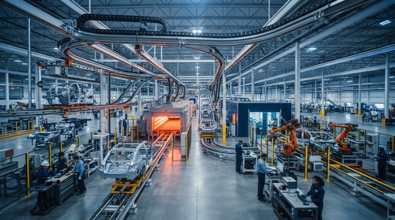
Stopping an entire assembly line simply because a single finishing cell needs three extra minutes is an operational flaw modern facilities can no longer afford. Power and free conveyor systems transform rigid manufacturing lines into decoupled, agile production networks that keep processes moving independently. If you manage complex workflows, you already know the frustration of floor-level forklift congestion, production bottlenecks caused by variable station cycle times, and the costly plant-wide stoppages triggered by conventional continuous-motion conveyors.
You don't have to sacrifice line throughput to gain operational flexibility. Discover how power and free conveyor systems provide asynchronous material routing, optimize vertical facility footprint, and streamline disparate processing cells without disruption. This 2026 engineering guide examines the mechanical separation between the power chain and the carrier trolley, evaluates overhead versus inverted layouts based on process hygiene and carrier stability, and details how dynamic inline buffering delivers a measurable return on investment.
Key Takeaways
- Power and free conveyor systems use a dual-track architecture that mechanically separates continuous chain propulsion from carrier movement, enabling true asynchronous material flow.
- Overhead and inverted layouts offer distinct operational advantages, balancing vertical plant clearance against robotic line access and overhead drip prevention.
- Integrated switches, dynamic accumulation dogs, and inline buffer loops eliminate processing bottlenecks caused by unequal station cycle times.
- Multi-zone routing capabilities seamlessly connect disparate manufacturing environments, including high-temperature curing ovens, automated paint cells, and final assembly lines.
- A thorough integration checklist covering structural roof loading, carrier center of gravity, and controls planning prevents common engineering setbacks during turnkey installation.
What Are Power and Free Conveyor Systems and How Do They Work?
At their foundational level, power and free conveyor systems separate mechanical propulsion from carrier motion. While conventional industrial conveyor systems permanently clamp loads to a motorized chain, a power and free configuration deploys two parallel tracks mounted one above the other. The dedicated upper channel houses a continuous drive chain, while the lower track guides independent wheeled load trolleys that carry the workpieces. This physical decoupling provides total control over individual parts, allowing facilities to hold, switch, and release products without shutting down primary drives.
The Mechanics of Dual-Track Engineering
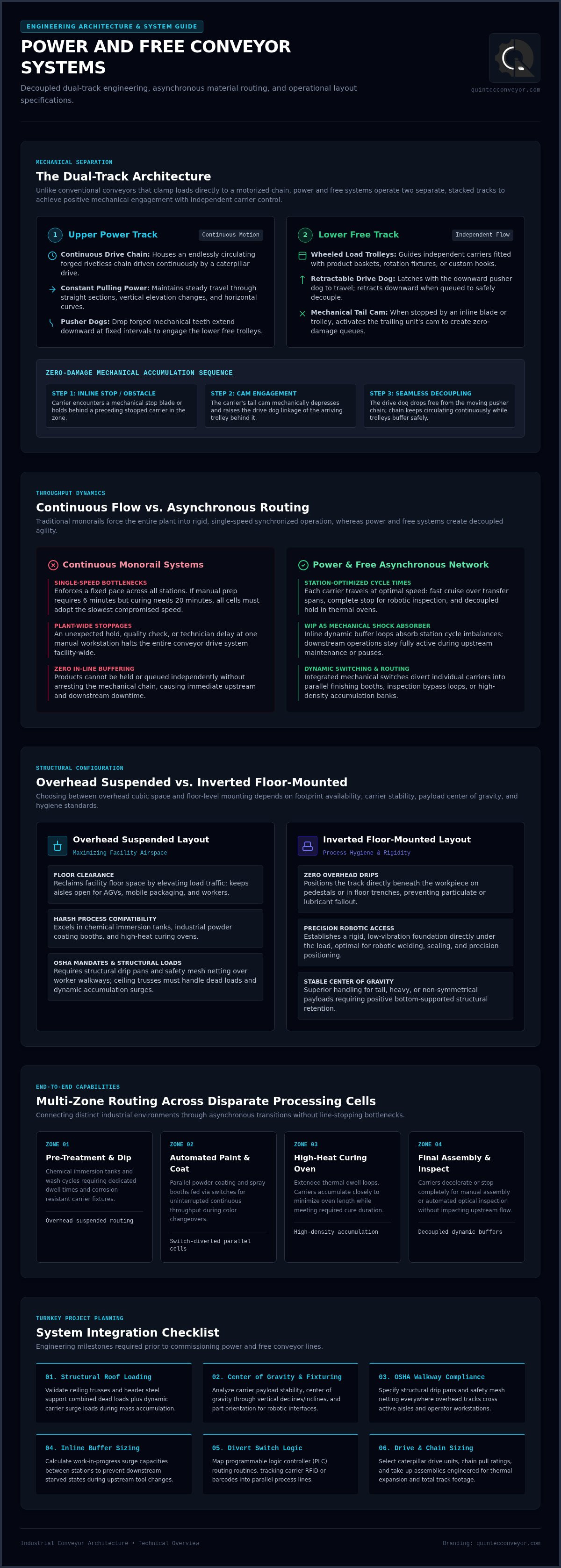
The dual-track architecture relies on positive mechanical engagement to deliver controlled forward travel:
- Upper Power Track: Contains an endlessly circulating forged rivetless chain supported by a caterpillar drive, providing constant pulling power through straight runs, horizontal turns, and vertical transitions.
- Lower Free Track: Supports independent carrier trolleys fitted with custom hooks, rotation fixtures, or product baskets.
- Pusher Dogs: Drop forged teeth extend downward from the moving power chain at fixed intervals, latching onto the retractable front drive dog of the lower trolley.
- Mechanical Accumulation: When a carrier encounters an inline stop blade or another carrier ahead, its tail cam raises the drive dog of the trailing unit. This instantly disengages the trolley from the power chain, creating an orderly, zero-damage queue.
Continuous Flow Versus Asynchronous Material Movement
Traditional monorail loops enforce rigid, single-speed cycles. If a technician needs six minutes to torque a sub-assembly while a curing oven requires twenty minutes of heat exposure, a fixed chain forces every station into a compromised, sluggish pace. Worse, an issue at a manual prep table halts the entire plant line.
Power and free conveyor systems eliminate this structural inflexibility through asynchronous material transport. Individual carriers move at the pace required by each cell. They can cruise at transit speed across transfer spans, divert into parallel finishing booths, stop dead for precision robotic inspection, and bank into dynamic buffers before final assembly. Work-in-progress inventory acts as a mechanical shock absorber. Downstream operations remain fully engaged during upstream maintenance, keeping operational output smooth and predictable.
Overhead vs. Inverted Configurations: Structural System Comparisons
Specifying power and free conveyor systems requires evaluating whether your process benefits more from vertical airspace or floor-level stability. While an overhead configuration lifts manufacturing traffic off the plant floor, an inverted layout establishes a rigid foundation directly below the product. Examining how these structural designs integrate with modular conveyor systems demonstrates that facility footprint, carrier payload, and process cleanliness dictate the final engineering choice.
Overhead Suspended Systems: Maximizing Floor Space
Overhead installations reclaim square footage by utilizing overhead cubic volume. Suspending the dual tracks above production cells keeps ground aisles completely open for automated guided vehicles, mobile packaging stations, and technicians. They excel in harsh finishing environments like chemical immersion tanks, industrial powder coating, and high-heat cure ovens. However, overhead routing requires compliance with OSHA conveyor safety regulations, mandating structural drip pans and safety mesh netting wherever carriers pass over worker walkways. Engineering teams must also conduct structural reviews to ensure ceiling trusses and header steel can withstand combined dead loads and dynamic carrier accumulation surges.
Inverted Floor-Mounted Systems: Precision and Cleanliness
Inverted systems position the track beneath the workpiece, mounting to structural pedestals or directly into floor trenches. This orientation eliminates particulate contamination because no lubricated chain runs above the component. It's the standard for automotive paint shops and cleanroom manufacturing where even a single oil drop ruins a surface. Floor-mounted systems also offer rigid stability, holding assemblies steady for robotic welding and vision inspection while granting operators unobstructed, 360-degree ergonomic access around the carrier.
Enclosed Track Versus Heavy-Duty I-Beam Load Ratings
Selecting track geometry establishes the weight envelope and physical footprint of the line:
- Enclosed Track: Encloses the chain within cold-formed steel tubing to prevent airborne dirt ingress. Designed for lightweight to medium parts, these setups typically handle unit loads up to 1,000 pounds, or up to 3,000 pounds using multi-trolley load bars. Their compact profiles allow tighter horizontal and vertical turn radii.
- Heavy-Duty I-Beam: Uses structural steel I-beams paired with drop-forged rivetless chains (such as X348, X458, or X678). Standard 4-inch setups carry 3,000 to 6,000 pounds per carrier, while 6-inch configurations manage severe payloads exceeding 20,000 pounds. These heavy systems demand substantial foundation anchor points and wider operational turn radiuses.
If you're weighing which layout matches your facility constraints, consulting an experienced integration team like Quintec Conveyors can help clarify the structural tradeoffs before fabrication begins.
Core Design Elements: Specifying Carriers, Switches, and Accumulation
Hardware geometry alone doesn't guarantee efficiency. The operational success of power and free conveyor systems hinges on how seamlessly carriers, routing hardware, and accumulation controls function as an integrated network. Engineering these physical components requires balancing dynamic load behaviors against the mechanical tolerances of the track.
Custom Carrier Geometry and Load Profiling
Carriers serve as the physical interface between track and workpiece. System designers must calculate dynamic center-of-gravity shifts, especially when loads traverse steep vertical inclines and declines. An unbalanced payload exerts uneven torsional load across trolley guide rollers, inducing premature track wear and causing mechanical binding on tight horizontal curves. For automated processing, carriers frequently incorporate mechanical indexers, spin collars, or articulating arms for multi-angle robotic presentation. In high-heat curing tunnels, carrier assemblies must also include thermal expansion joints so pivot points don't seize under extended thermal cycles.
Track Switches, Drop Sections, and Elevation Routing
Automated tongue and frog switches dynamically divert carriers into parallel process spurs, bypass loops, or offline inspection zones. Managed by programmable logic controllers communicating through fieldbus protocols, these switches route carriers based on automated barcode or RFID scans. When elevation shifts are required, motorized or counterbalanced drop sections lower carriers directly to floor-level operator stations or chemical tanks. Mechanical interlocks and secondary limit stops compliant with the ASME B20.1 safety standard for conveyors prevent carriers from ever advancing into an open vertical gap or misaligned track branch.
Dynamic Buffer Zones and Non-Contact Accumulation
Asynchronous manufacturing relies on dynamic buffer zones to absorb cycle-time variances between rapid assembly operations and extended thermal or chemical processes. Pneumatic stop blades act as inline gates; when raised, they compress the trolley front dog downward, allowing the continuously moving chain pusher dogs to bypass the carrier without stopping the main drive. For painted components, delicate electronics, or heavy assemblies prone to inertia impact, non-contact accumulation systems prove indispensable. These setups use secondary linkage bars or ultrasonic field sensors to disengage trailing trolleys several inches before bumper impact, completely eliminating part-to-part collision damage.
High-Impact Industrial Applications Across Modern Facilities
Modern production facilities run multi-stage operations with drastically different processing speeds. While an automated wash cycle cleans parts in ninety seconds, subsequent chemical coatings, primer applications, and heat cures require varying dwell periods. Power and free conveyor systems excel in these environments because they act as dynamic buffers between isolated process zones. Pairing overhead pathways with comprehensive warehouse design services ensures overhead conveyance synchronizes directly with floor-level logistics rather than operating as an isolated mechanical island.
Finishing Systems, Paint Booths, and Curing Ovens
Surface preparation and coating lines demand precise transit timing. Power and free layouts route loaded carriers through automated pre-wash tunnels, pull them into parallel spray booths at measured application rates, and accumulate them inside convection cure ovens. Variable-speed track segments adjust carrier velocity dynamically depending on the coating recipe. Because workpieces can bank tightly inside oven loops without halting the upstream wash line, thermal zones operate at peak volumetric density while conserving heat energy.
Automotive and Heavy Machinery Sub-Assembly
Automotive powertrains, agricultural equipment, and heavy industrial weldments rarely move along single-line paths. Complex component trees require sequenced merging into main assembly cells. Asynchronous loops permit workers to hold large frames indefinitely for wiring harness installation or torque verification without starving downstream workstations. These overhead circuits transfer heavy sub-assemblies across long factory spans, interfacing with floor-mounted industrial conveyor systems through automated vertical lifters to create seamless multi-level production workflows.
Dynamic Overhead Staging and Warehouse Buffering
High-mix manufacturers face continuous floor-level congestion when relying solely on forklifts or standard pallet jacks to transport work-in-progress materials. Modern facilities reclaim valuable ceiling space by converting overhead track loops into live inventory buffers:
- Live WIP Storage: Finished sub-assemblies queue overhead until required, freeing up ground square footage for value-add manufacturing.
- Automated Kit Sortation: Barcode-linked diverters release specific carriers down to packaging and palletizing stations on demand, eliminating staging errors.
- Traffic Reduction: Moving high-volume component transit into the plant trusses eliminates cross-aisle forklift traffic, creating safer, cleaner shop-floor pathways.
To eliminate bottlenecks across your production cells and optimize floor capacity, partner with Quintec Conveyors to design and integrate a turnkey material handling system tailored to your facility.
System Integration Checklist: Planning and Executing Installation
Executing successful installations of power and free conveyor systems requires rigorous pre-engineering and phased deployment. Rather than treating hardware as standalone equipment, engineering teams must treat the conveyor as a fully integrated logistics network. Choosing an experienced conveyor system integrator ensures your structural capacity, controls architecture, and maintenance workflows align seamlessly from initial modeling through final commissioning.
Structural Load Auditing and Building Infrastructure
Before installing track sections, engineers must verify that the facility structure can support the installation. Load calculations must account for static dead weight, maximum live payloads, and the dynamic shock loads that occur when heavy carriers bank into accumulation queues. If building roof trusses lack the point-load capacity required for overhead suspension, the system requires independent, floor-supported structural steel header frames. Detailed site planning also ensures the layout respects building expansion joints, preserves sprinkler spray clearances, and maintains clear emergency egress corridors throughout the facility.
Controls Architecture and Warehouse Execution Integration
Modern conveyor routing depends on responsive electrical controls and field communications. Programmable logic controllers (PLCs) coordinate field sensors, pneumatic stop cylinders, and RFID tracking antennas at every merge, switch, and drop section. This controls layer interfaces directly with plant-wide Manufacturing Execution Systems (MES) to automate part routing based on real-time station availability. Safety integration must incorporate independent emergency-stop zones, mechanical anti-runaway stops along inclined tracks, and visual indicators at remote restart points.
Turnkey Commissioning, Testing, and Lifecycle Maintenance
Commissioning begins with unloaded dry runs to verify track alignment, followed by testing with weighted prototype carriers to simulate peak operating strain:
- Engagement Tolerances: Technicians inspect the engagement depth between the power chain pusher dogs and trolley front dogs across all drive zones.
- Switch Interlocks: Commissioning teams stress-test automated diverters and vertical drop sections under maximum cycle speeds to verify mechanical lockouts.
- Preventative Maintenance Protocols: Integration teams establish structured maintenance routines, focusing on metered automatic chain lubrication, chain tension monitoring, and regular trolley dog wear inspections.
A methodical integration process protects your capital investment, ensuring your production line delivers steady operational reliability for years to come.
Transform Your Manufacturing Flow with Intelligent Material Handling
Industrial facilities can't afford the rigid constraints of traditional, fixed-speed transport. Implementing power and free conveyor systems provides the mechanical agility required to decouple complex assembly stages, buffer work-in-progress inventory overhead, and maintain consistent cycle times across disparate processing cells. Whether you deploy an overhead arrangement to reclaim floor area or an inverted configuration for pristine robotic finishing, rigorous structural planning and controls integration turn complex material routing into a lasting operational asset.
Navigating track geometry, dynamic load profiles, and automated PLC switching demands an experienced integration partner. Backed by over 100 years of collective industry experience across complex systems engineering, Quintec Conveyors delivers comprehensive turnkey capabilities spanning system design, controls architecture, and national installation. Our teams bridge specialized overhead conveyance with holistic automated warehouse flows to keep production running smoothly. Connect with Quintec Conveyors to engineer your custom material handling system and build an agile, scalable operation today.
Frequently Asked Questions
How does a power and free conveyor differ from a standard monorail conveyor?
A standard monorail fixes load trolleys directly to the motorized chain, forcing every carrier along the loop to travel at an identical speed. If one workstation stops, the entire system stops. Power and free conveyor systems use two tracks: an upper power rail driven by a continuous chain and a lower track carrying independent trolleys. Mechanical dogs engage and disengage on demand, allowing individual carriers to halt, accumulate, or switch lines independently without interrupting the primary drive.
What is the maximum payload capacity a power and free system can support?
Payload capacity depends entirely on the track profile and trolley configuration selected for the application. Compact enclosed-track systems support lighter components up to 1,000 pounds per carrier. Heavy-duty structural I-beam systems handle significantly larger payloads. A standard 4-inch I-beam track easily manages 3,000 to 6,000 pounds per carrier, while 6-inch installations paired with multi-trolley load bars routinely convey heavy machinery frames and automotive assemblies exceeding 20,000 pounds.
How do accumulation dogs function when carriers queue behind one another?
Accumulation dogs use a mechanical pivot linkage that converts contact into vertical disengagement. Each carrier trolley has a spring-loaded front drive dog and an elevated rear tail cam. When a leading carrier stops at an inline pneumatic gate, the trailing trolley's front dog rides up over the leader's rear cam. This action pushes the front dog downward, releasing it from the overhead chain pusher dog and allowing the drive chain to bypass smoothly overhead.
Can power and free conveyor lines be integrated with existing facility robotics?
Yes, power and free systems readily integrate with industrial robotics through programmable logic controllers. Stop blades, pneumatic shot pins, and carrier stabilizing clamps lock the trolley into a precise physical datum within the robotic work envelope. Once secured, robotic arms perform high-precision spot welding, sealant dispensing, or vision inspection. After the automated routine finishes, the controller signals the conveyor stop blade to drop, re-engaging the trolley with the drive chain.
What are the main advantages of choosing an inverted conveyor over an overhead layout?
Inverted conveyor configurations mount the track beneath the workpiece, delivering rigid carrier stabilization and superior process hygiene. Because the motorized drive chain and lubricated trolleys sit below the product, no oil, graphite, or metal shavings can drop onto painted surfaces or sensitive electronic components. Inverted designs also provide 360-degree ergonomic access around the carrier, making them ideal for high-precision robotic finishing, manual assembly cells, and cleanroom environments.
How are carriers tracked and routed through multi-line track switches?
Carriers are tracked using high-temperature passive RFID tags, optical barcodes, or vision sensors mounted directly to the trolley chassis. As a carrier approaches a track split, an inline reader scans the tag and communicates with the central PLC or Manufacturing Execution System. The controls software instantly queries the production schedule, checks line capacities, and fires a pneumatic actuator to set the tongue switch, directing the carrier into the appropriate process spur.
What routine maintenance do power and free conveyor systems require?
Maintaining power and free conveyor systems centers on chain tension monitoring, controlled lubrication, and mechanical wear checks. Maintenance teams must inspect caterpillar drive dogs, check take-up unit air pressure, and verify trolley front dog wear profiles to prevent slip. Modern installations deploy automated micro-dose lubrication systems that deliver high-temperature synthetic oil to chain pins and open trolley bearings, preventing premature chain stretch, tracking misalignment, and unpredicted production downtime.